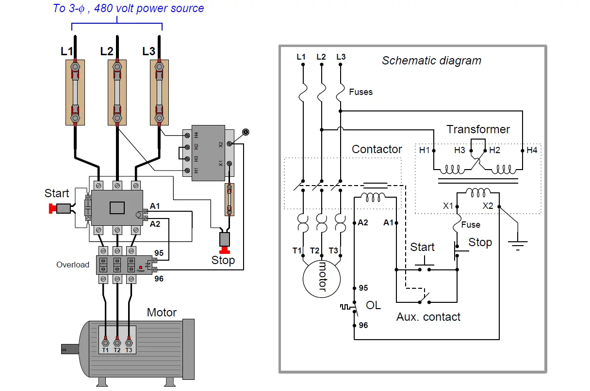
Cool Up And Down Motor Control Circuit

Power Control Circuit For Forward And Reverse Motor Electrical Circuit Diagram Electrical Diagram Circuit Diagram
Power Control Circuit For Forward And Reverse Motor Electrical Diagram Connecting Multiple Lights To One Switch Boss Rt3 V Plow Wiring Harness
Forward Reverse 3 Phase Ac Motor Control Circuit Diagram Electrical Engineering Updates Circuit Diagram Electrical Circuit Diagram Electrical Diagram

Forward Reverse 3 Phase Ac Motor Control Circuit Diagram Electrical Engineering Updates 460 Volt Wiring Air Compressor

Pin On Electronics Projects
Pin On Electronics Projects 1 Way Switch Diagram 12 Lead Motor Wiring
Forward Reverse Motor Control Diagram Reversing Contactors Youtube Electrical Diagram Delta Electronics Basics
Forward Reverse Motor Control Diagram Reversing Contactors Youtube Electrical Delta Electronics Basics Tp Link Switch Install With Only Two Wires Magnetic Starter
Full Voltage Reversing 3 Phase Motor Diagram Electrical Circuit Diagram Electronic Engineering Electrical Diagram

Full Voltage Reversing 3 Phase Motor Diagram Electrical Circuit Electronic Engineering Photocell Sensor Wiring Ups

Speed Control Of Dc Motor Using Arm Processor Edgefx Engineering Projects Electronics Projects Speed
Speed Control Of Dc Motor Using Arm Processor Edgefx Engineering Projects Electronics Contactor Switch Wiring Pump Diagram
Speed Control Of Dc Motor Using Arm Processor Edgefx Engineering Projects Electronics Projects Speed

Remind your students that the purpose of an overload heater is to provide a thermal analogue of the electric motor itself.

Up and down motor control circuit. 220 volt motor speed control. Motor speed control robotics stepper motor control. 3 easy to build speed controller circuits for dc motors are presented here one using mosfet irf540 second using ic 555 and the third concept with ic 556 featuring torque processing.

What follows is a simple program for the cytron motor controller to ramp up and down the motor s speed in one direction and then the other. Thus motor reversal is not built into the motor. 12 volt or 24 volt dc pulse width modulator.

Can be used for controlling the rpm of a ball mill and star rolling machine motors or electric drills. This circuit can be used as a light dimmer or dc motor speed controller. Ideally the heater heats up and cools down at the exact same rate as the motor.

H bridges are used in many different applications. If we wanted to keep the motor running even after the operator takes his or her hand off the control switch es we could change the circuit in a couple of different ways. To control the direction of the spin of dc motor without interchanging the leads you can use a circuit called an h bridge.

Dc motors forward and backward this circuit drives small dc motors up to about 100 watts or 5 amps or 40 volts h bridge. The alltrax controller handles currents so large it cannot effectively and safely use a solid state h bridge to reverse motor direction. Already we discussed about the basics of permissive and interlock circuits in previous post also discussed about the basic motor control logic using forward reverse control.

Add tip ask question comment download. The interlock contacts installed in the previous section s motor control circuit work fine but the motor will run only as long as each push button switch is held down. An h bridge is an electronic circuit that can drive the motor in both directions.

Rev For Three Phase Motor Connection Power And Control Diagrams Electrical Circuit Diagram Electrical Projects Circuit Diagram
Rev For Three Phase Motor Connection Power And Control Diagrams Electrical Circuit Diagram Projects Basic Wiring Symbols Manual Transfer Switch
Pin On Engineering

Pin On Engineering Wiring Wiper Motor To Toggle Switch Up Trailer Plug

Motor Control Circuit Wiring Instrumentation Tools
Motor Control Circuit Wiring Instrumentation Tools Blower Diagram Hoppy Trailer Plug
Starting Capacitor Wiring Diagram With Single Phase Motor Start At Electrical Circuit Diagram Circuit Diagram Capacitors

Starting Capacitor Wiring Diagram With Single Phase Motor Start At Electrical Circuit Capacitors 3 Wire Thermostat Color Code Yamaha Outboard Ignition Switch

How To Set Up Limit Switches With A Wired Dpdt Switch For Reverse Forward Controls Switch Switches Circuit Design

How To Set Up Limit Switches With A Wired Dpdt Switch For Reverse Forward Controls Circuit Design Replacing Gfci Breaker 2 Gang Wiring Diagram

Electronics Motor Controller Circuit Diagram Circuit Diagram Electronic Circuit Projects Electronic Gadgets For Men
Electronics Motor Controller Circuit Diagram Electronic Projects Gadgets For Men Color Code Trailer Wiring 7 Way Ceiling Fan 3 Switch
Pin On Latest Electronics Projects
Pin On Latest Electronics Projects Six Wire Stepper Motor Capacitor Start Run Induction With Neat Diagrams
Pin On Diy

Pin On Diy 50 Hp Mercury Outboard Wiring Diagram Reversible Motor

12v 24v Pwm Motor Controller Circuit Using Tl494 Irf1405 Basic Electronic Circuits Circuit Diagram Circuit

12v 24v Pwm Motor Controller Circuit Using Tl494 Irf1405 Basic Electronic Circuits Diagram Ac Motovario Wiring