Perfect Ballast Ignitor Capacitor Wiring

If not the arrangement will not function as it ought to be.
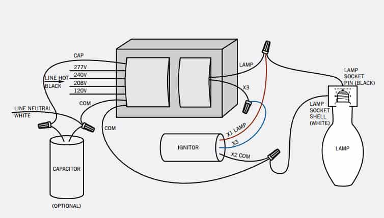
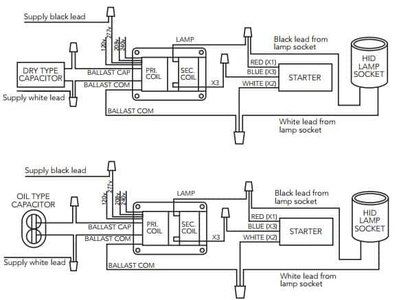
Ballast ignitor capacitor wiring. In addition to these three the hps ballast should also be wired to a bulb and socket. The capacitor i have 12 micro farads 250v 50 60hz is suitable for the ballast and is wired correctly in the photograph. The transformer the capacitor and the ignitor.
It is multi tapped for 380 400 415v. The reactor ballast is electrically in series with the lamp. Lamp current is 8 8a with a total circuit load of 2085w.
There is no capacitor involved with the operation of the lamp. Each component ought to be placed and connected with different parts in particular manner. Very much a general purpose ballast it can be used on.
There are also some helpful wiring diagrams although these vary dependent on the type of ignitor to be used. Otherwise the structure won t function as it ought to be. There are three basic parts inside the ballast.
When purchasing individually make sure to buy the correct rating for the home usually 120v in most homes. The capacitor used is a 40uf 440v. Also obtain a wiring diagram for the ballast.
Fluorescent ballast wiring diagram 8 foot fluorescent ballast wiring diagram advance fluorescent ballast wiring diagram compact fluorescent ballast wiring diagram every electric arrangement is composed of various diverse pieces. In this situation the reactor ballast performs only the current limiting functions since the voltage necessary to initiate the ignitor pulses and start and sustain the lamp comes directly from the input voltage to the fixture. Each of these parts can be bought separately.


